Drawing geometry
The package Orka.Rendering.Drawing provides several procedures
to draw geometry to the currently used framebuffer.
There are several ways to draw geometry:
- Vertices can be drawn with or without indices
- Vertices can be drawn directly or indirectly
For each of the possible combinations are different procedure is used:
| Direct | Indirect | |
|---|---|---|
| Without indices | Draw |
Draw_Indirect |
| With indices | Draw_Indexed |
Draw_Indexed_Indirect |
Because Orka supports only programmable vertex pulling, the buffer containing the vertices must be binded as an SSBO to a binding point before it can be drawn using one of the procedures mentioned above. See Binding vertex data for more information on how to bind a buffer.
For example, one triangle consisting of three vertices can be drawn using:
Orka.Rendering.Drawing.Draw (GL.Types.Triangles, 0, 3);
The optional parameter Instances can be specified to draw multiple instances.
In the vertex shader, gl_VertexID can be used to get the vertex ID.
Indices
Since vertices in geometry are often used by multiple primitives (triangles or lines), it is recommended to use indices to avoid having to repeat the data for a vertex multiple times in the vertex buffer. The indices are used to refer to vertices (the data of a vertex includes information like the position, normal, and texture coordinates). These indices are stored in a vertex buffer. This buffer is automatically binded by one of the above procedures.
Procedure Draw_Indexed is used to draw geometry with an index buffer.
For example, 10 instances of the geometry (consisting of triangles)
can be drawn using:
Orka.Rendering.Drawing.Draw_Indexed
  (Triangles, Buffer_Indices, 0, Buffer_Indices.Length, Instances => 10);
Indirect drawing
Indirect drawing is useful if the draw calls are generated by a compute
shader on the GPU.
Inserting a barrier and then a single call to Draw_Indexed_Indirect is
sufficient to draw instances of multiple objects.
When performing frustum and occlusion culling on the GPU, millions of objects
can be rendered without much work done on the CPU itself.
When drawing indirectly, the actual draw calls are stored in a buffer
containing elements of the type Arrays_Indirect_Command or Elements_Indirect_Command,
defined in the package GL.Types.Indirect.
Generally, it is recommended to use the procedure Draw_Indexed_Indirect
so that an index buffer is used.
The procedure Draw_Indexed_Indirect requires a parameter Index_Buffer
for the index buffer, and a Buffer containing the draw commands.
Two other instances of the procedure exist: one with an Offset and Count,
both of type Natural, and another with just Count being another buffer.
The Count buffer contains the number of draw commands that must be rendered.
It is useful if this buffer is written to by a compute shader on the GPU.
Without this extra buffer, the procedure Draw_Indexed_Indirect uses the
length of the buffer containing the commands (Buffer.Length).
Indirect drawing can be quite complicated.
The package Orka.Rendering.Buffers.MDI can be used to create
the necessary vertex, index, and command buffers.
Example
As an example, three instances of an object, consisting of two parts can be rendered to the screen. In this example, each part is just one triangle; one pointing downwards and one pointing upwards.
The vertices and indices are declared as following:
Vertices_1 : constant Orka.Float_32_Array
  := (-0.25,  0.5,
      -0.75, -0.5,
       0.25, -0.5);

Vertices_2 : constant Orka.Float_32_Array
  := (-0.25,  0.5,
       0.25, -0.5,
       0.75,  0.5);

Indices_1 : constant Orka.Unsigned_32_Array := (0, 1, 2);
Indices_2 : constant Orka.Unsigned_32_Array := (0, 1, 2);
Then create a Batch object:
Batch_1 : Batch := Create_Batch
  (Orka.Types.Single_Type, Orka.Types.UInt_Type, 2,
   Vertices_1'Length + Vertices_2'Length,
   Indices_1'Length + Indices_2'Length);
After the Batch object has been created, vertices and indices can be
written to its buffers:
procedure Append_Draw_Call
  (Instances : Natural; Vertices : Orka.Float_32_Array; Indices : Orka.Unsigned_32_Array)
is
   Vertex_Elements : constant := 2;

   procedure Append_Vertices (Offset, Count : Natural) is
   begin
      Batch_1.Data.Write_Data (Vertices, Offset => Offset * Vertex_Elements);
   end Append_Vertices;

   procedure Append_Indices (Offset, Count : Natural) is
   begin
      Batch_1.Indices.Write_Data (Indices, Offset => Offset);
   end Append_Indices;
begin
   Batch_1.Append (Instances, Vertices'Length / Vertex_Elements, Indices'Length,
     Append_Vertices'Access, Append_Indices'Access);
end Append_Draw_Call;
Two instances of the first object (a triangle pointing downward) are added, and three instances of the second object:
Append_Draw_Call (2, Vertices_1, Indices_1);
Append_Draw_Call (3, Vertices_2, Indices_2);
Batch_1.Finish_Batch;
Rendering
The instances can then be rendered by binding the vertex buffer and then
calling Draw_Indexed_Indirect:
Batch_1.Data.Bind (Shader_Storage, 0);

Orka.Rendering.Drawing.Draw_Indexed_Indirect
  (Mode         => GL.Types.Triangles,
   Index_Buffer => Batch_1.Indices.Buffer,
   Buffer       => Batch_1.Commands.Buffer);
In the vertex shader, gl_VertexID and gl_InstanceID
should be used to write a position to gl_Position.
In the fragment shader, the parts and instances can be drawn using the:
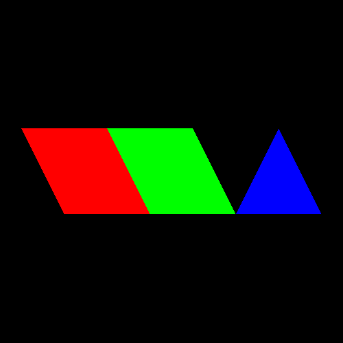
- Draw ID (with
gl_DrawIDARB) - Instance ID (with
gl_InstanceID) - Object ID (with
gl_BaseInstanceARB + gl_InstanceID)
gl_DrawIDARB and gl_BaseInstanceARB require the extension
ARB_shader_draw_parameters:
#extension GL_ARB_shader_draw_parameters : require
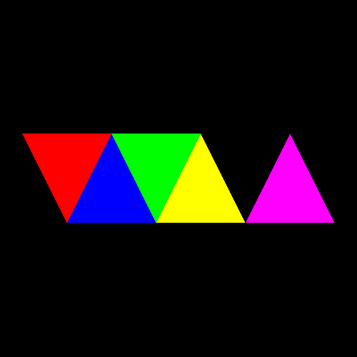
Creating an array of the colors red, green, blue, yellow, magenta, cyan, or white in the fragment shader, then choosing a color in one of the three ways mentioned above, the following results are obtained.
Draw ID:
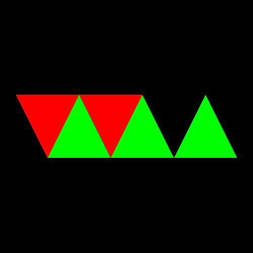
Instance ID:
Object ID: